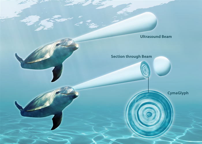
In ultrasonic testing (UT), very short ultrasonic pulse-waves with center frequencies ranging from 0.1-15 MHz and occasionally up to 50 MHz are transmitted into materials to detect internal flaws or to characterize materials. A common example is ultrasonic thickness measurement, which tests the thickness of the test object, for example, to monitor pipework corrosion.
Ultrasonic testing is often performed on steel and other metals and alloys, though it can also be used on concrete, wood and composites, albeit with less resolution. It is a form of non-destructive testing used in many industries including aerospace, automotive and other transportation sectors.
How it works
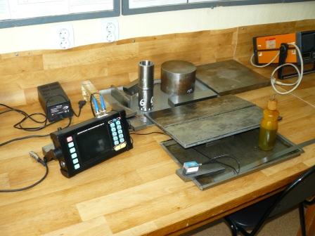
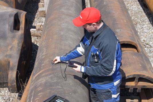
In ultrasonic testing, an ultrasound transducer connected to a diagnostic machine is passed over the object being inspected. The transducer is typically separated from the test object by a couplant (such as oil) or by water, as in immersion testing. However, when ultrasonic testing is conducted with an Electromagnetic Acoustic Transducer (EMAT) the use of couplant is not required.
There are two methods of receiving the ultrasound waveform: reflection and attenuation. In reflection (or pulse-echo) mode, the transducer performs both the sending and the receiving of the pulsed waves as the "sound" is reflected back to the device. Reflected ultrasound comes from an interface, such as the back wall of the object or from an imperfection within the object. The diagnostic machine displays these results in the form of a signal with an amplitude representing the intensity of the reflection and the distance, representing the arrival time of the reflection. In attenuation (or through-transmission) mode, a transmitter sends ultrasound through one surface, and a separate receiver detects the amount that has reached it on another surface after traveling through the medium. Imperfections or other conditions in the space between the transmitter and receiver reduce the amount of sound transmitted, thus revealing their presence. Using the couplant increases the efficiency of the process by reducing the losses in the ultrasonic wave energy due to separation between the surfaces.
Generation and reception of ultrasound
There are several methods to generate ultrasonic waves in the studied object. The most common is the use of the piezoelectric effect. In this case, the ultrasound radiation is performed by using a converter which converts the power into acoustic oscillations by means of the inverse piezoelectric effect. The reflected signals are trapped in the piezoceramic plates because of the direct piezoelectric effect are converted into electric, which are recorded by measuring circuits.
Electromagnetic-acoustic (EMA) method is also used, based on the application of strong alternating magnetic fields to the metal. Efficiency of this method is much lower than that of the piezoelectric, but it can work through the air gap and needs no special requirements for surface quality.
Classification of researches
Reflective methods
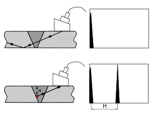
Pulse-echo method of testing the weld joint without defect (top) and with defect (bottom). In the right part of the image the screen of the flaw detector shows a picture with generated pulse (top) and the pulse from the defect (bottom) on it.
- Echo method or pulse-echo method - the most common: converter oscillates (i.e. acts as a generator) and he also receives reflected from defects echoes (receiver). This method is widely used due to its simplicity, because for control requires only one inverter, hence the manual control is no need for specially adapted for fixing it (as, for example, in a diffraction-time method) and combining acoustic axes using two converters. In addition, it is one of the few methods of ultrasonic testing, allowing a sufficiently accurate determination coordinates of the defect, such as the depth and position in the test object (relative to the transmitter).
-
Mirror
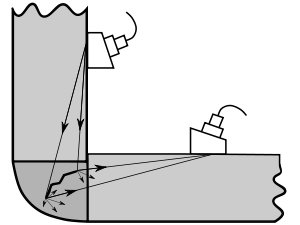
or echo-mirror method - uses two converters on one side of the piece: the generated oscillations
are reflected from the defect to the side of the receiver. In practice, the
defect detection is used to control surface arranged perpendicularly, such as
cracks.
- diffraction-time method - uses two converters on one side of the part, opposite each other. If a defect has sharp edges (such as cracks), the vibrations at the ends of the defect diffracted and reflected to all sides, including the side of the receiver. Flaw detector records the time of arrival of the two pulses with a sufficient amplitude. The display simultaneously displays the flaw signal from both the top and bottom edges of the defect, thereby possible a sufficiently accurate determination of height of the defect. The method is flexible enough. it allows ultrasonic testing of welds on any difficulty, but requires special equipment to fix the converters as well as flaw detector, able to work in this mode. Furthermore, the diffracted signals are weak.
- Reverbation method - based on a gradual attenuation of the signal in the control object. When controlling two layer structure in the case of high-quality compound layer, part of the energy of the first layer will go to the second, so there will be less reverb. In the opposite case multiple reflections will be observed on the first layer, the so called forest. Method is used to control various types of clutch surfacing, for example surfacing Babbitt with iron base. The main disadvantage of this method is the registration of flaw detector echoes from the border the two layers. Cause of these echoes is the difference in speed of elastic waves in materials of different compounds and their specific acoustic resistance. For example, on the border of babbitt-steel, a constant appears echo even in places qualitative coupling. Due to structural features of some products, quality control of joining materials by reverbation method may not be possible because of the presence on the screen of flaw detector echoes from the border connections.
- Acoustic microscopy due to increased input frequency of ultrasonic beam focusing and its application is capable of detecting defects whose dimensions do not exceed tenths of a millimeter.
- Coherent method - apart from the two main parameters of echo such as amplitude and time of arrival is an optional phase of the echo signal. Using coherent method, but rather a set of identical converters operating in phase, allows to obtain an image of the defect, which is close to the real. When using special converters, such as traveling wave converter or its modern equivalent - a phased array converter, the method can significantly reduce the time spent on the inspection of the product.
Through transmission method
Passing methods are observation of changes in the parameters of the ultrasonic vibration transmitted through the object of control, so-called cross-cutting vibrations. Originally applied for continuous emission monitoring and change its amplitude vibrations through regarded as a defect in the controlled object, the so-called sound shadow. Hence came the name of the shadow method. Eventually replaced by continuous emission pulse, and in addition to the fixed parameters of the amplitude also added phase spectrum and pulse arrival time and there are other methods of passing. The term shadow lost its original meaning and has come to mean a method of through transmission.
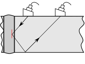
- Shadow - uses two converters, which are two sides of the the studied detail on one acoustic axis. In this case, one of the converters oscillates (generator), and takes them to the second (receiver). Indicate the presence of a defect will be a significant reduction in the amplitude of the received signal, or its disappearance (defect creates an acoustic shadow).
- Mirror-shadow - is used to control parts with two parallel sides, the development of the shadow method: analysis of reflection from the opposite face of the part. An indication of the defect, as in the shadow method, is considered disappearance of the reflected vibrations. The main advantage of this method is distinct from a shadow access to the workpiece on one side.
- Time-shadow is based on the pulse delay time spent on rounding defect. Is used for control refractory brick or concrete.
- The multiple shadows method is similar to the shadow, with the exception that the ultrasonic wave passes through parallel surfaces of the product several times.
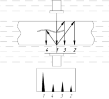
- Echo-through method uses two converters located on opposite sides of a control object opposite each other. In case of absence of defect on the flaw detector through signal is observed and doubly reflected from the walls of the object of control. In the presence of translucent defect reflections of through signals from the defect are also observed.
Ultrasound testing does not destroy or damage the test sample, which is its main advantage. It is suitable for control of products from a variety of materials, both metals and non-metals. It is also possible to allocate a high rate study at low cost and hazards to humans (as compared to X-ray testing) and the high mobility of the ultrasonic flaw detector.
Features of ultrasonic testing
Typically, ultrasonic testing cannot answer the question about the actual size of defect but its reflectivity in the direction of the receiver. These values are correlated, but not for all types of defects. Furthermore, some defects are virtually impossible to detect by ultrasound because of their nature shape or location in the control object.
Producing reliable ultrasonic testing of coarse-grained metals, such as iron or austenitic welded joint (thickness greater than 60 mm) due to the large scattering and strong ultrasonic attenuation is almost impossible. In addition, the difficult control of small parts or parts with complex shapes.
