Metallographic survey of the metal and welded joints
Metallography research - is a set of tests and analytical activities aimed at examining the macrostructure and microstructure of metals, the study of the formation of structure and dependency structure influence on the mechanical, physical - mechanical, electrical and other properties of the metal.
Metallographic research methods of metals and welds allow to determine the size, shape and relative position of the crystals, as well as non-metallic inclusions, cracks, shells, pores, fistulas, etc.
There is a macroscopic and microscopic methods for studying the structure of metals.
Macroscopic method - study of the structure of metals and welds to the naked eye or with magnifying glass, giving an increase in 5-30 times. Macroanalysis is able to detect shells, slag inclusions, discontinuities of metal, cracks and other defects in the structure of the alloy, chemical and structural heterogeneity.
Microscopic analysis of the metals is in the investigation of their structure using optical or electron microscopes on specially prepared samples. Microanalysis techniques determine the shape and size of the crystal grains, exhibit changes in the internal structure of the alloy under the influence of heat treatment or mechanical impact on the alloy, microcracks and more.
Since all metals are not transparent, their structure can be studied at the breaks or specially prepared thin sections. Study of the structure by factography for fractures is often used when analyzing the causes of the destruction of parts of machines, equipment and steel structure elements. Macro-method is also used for an approximate determination of the depth of hardened tool steels zone, cemented layer depth, etc.
Studying macrostructure of metal is usually carried out on specially prepared thin sections. In this case, the item or article is cut. Surface, which should be studied thoroughly treated to become plane on a machine tool. If the item is cut by a gas burner, it is necessary to remove the entire metal layer, in which the change in structure is a result of heating of the burner flame. Typically, the depth of this layer for steel used in boiler and turbine construction does not exceed 10-12 mm. Then, the surface should be flat on the grinder and sandpaper. To identify the structure of the metal it must be etched. In the process of etching the crystals dissolve at different rates as they are oriented differently relative to the surface under study. The properties of the crystals, including solubility and chemical reagents are different in different directions. The boundaries between the crystals contain a higher percentage of admixtures, so they dissolve faster than crystals. Sometimes etching receives different colors of alloy structural components. Therefore, as a result of the etching can get a clear picture of the crystal structure of the metal.
Etchant erodes cracks, rolled slivers, porous areas stronger than base metal.
In thermotechnics macrostructure of steam pipelines welds is examined. This pipelines transport the superheated steam with temperature higher than 450 ° C regardless of the pressure and pipes through which water or saturated steam is transported at temperatures above 120 ° C and a pressure of more than 8 MN/m2 (80 am). Control of macrostructure welds required for the remaining elements of the steam boiler operating at a wall temperature above 450 ° C or regardless of the wall temperature at a pressure above 4 MN/m2 (40 am).
During metallographic research reveals macro-and microscopic defects in the weld: lack of fusion, cracks, pores, slag inclusions, and also establish the metal structure.
Sample for metallographic examination is cut from the welded joint, perpendicular to the axis of the joint. The sample should include both joint and the heat affected zone.
Cracks in the base metal weld not welded layers, large slag inclusions, lack of penetration above the norm is not allowed. Lack of penetration shall not exceed at sided welding without backing rings 15% of the wall thickness; if the wall thickness exceeds 20 mm - 3 mm.
Visible to the naked eye small slag inclusions and pores in an amount of not more than five pieces of 1 cm2 of cross-sectional area of joint are allowed. The maximum size of a single line defect on the greatest length should not be more than 1.5 mm, and the sum of the maximum linear dimensions of all defects - no more than 3 mm.
Microscopic analysis of the structure of metals and welds allows observing directly their structure with increasing up to 2000 times. Usually an increase from 100 to 800 times is used.
Study of the structure of the metal is performed in a microscope using reflected light. Metal sample is thoroughly treated to become plane on a machine tool, by grounding and polishing. After such preparation it reflects the rays like a mirror. Cracks, pores, nonmetallic inclusions are visible on not etched thin section. To reveal the grain boundaries and individual structural components, thin section is etched. For the etching of the microstructure of steel and welded joints 3-5% solution of nitric acid in alcohol is often used.
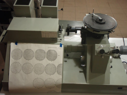
Microstructure studies and photographing is performed with a special stationary metallographic microscope. Photo 1 shows a microscope Neophot 2 is inverted photomicroscopy with reflected light intended for metallographic microscopy with computerized playback of results.
Thermal power plants must be monitored for the structure of the metal of steam pipelines in the initial state as well as after different periods of operation. This control is carried out on samples cut from the steam line, using portable microscopes, installed directly on the steam line, as well as using the prints.
In the case of the last two methods is no need for cutting out samples for metallographic studies of steam line. Thin section is prepared directly on the pipe (on the object of study). The oxide scale and the surface of metal layer decarbonized during heat treatment with depth of 0.5-1 mm are removed by means of portable sanding disc, which is driven by a pneumatic or electric power.
Etching is often performed with a 4% solution of nitric acid in alcohol. To identify the microstructure better polishing and etching process is typically repeated several times.
Thus prepared thin section can be studied directly on the site using a portable optical microscope, or by removing the mold from the section and already exploring it with stationary microscope in a laboratory.
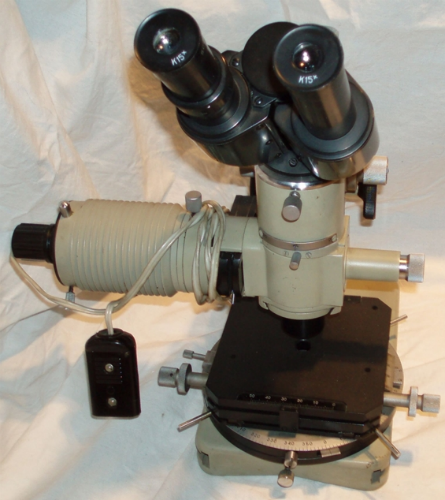
We have a portable Metallograph type MMU-3U (photo 2), allows the study of the microstructure with an increase up to 400 times.
While studying the causes of the destruction of various parts during the operation test specimens are cut near the fracture and at a distance from it, so that you can determine the presence of any abnormalities in the structure of the metal. In addition, the structure is studied in the longitudinal and transverse directions.
1. Results of macroscopic analysis
(for example, overlaying of distance ring lower tap of the reactor, catalytic reforming).
While macroexamination of overlaying in distance ring crack of backbone is revealed with depth ~ 11mm photos 1 and 2. Disclosure cracked up to 0.19 mm. Nature of cracking fracture is shown in photo 3. The crack tip is sharp, ragged, indicating the dynamics of its development. Crack in the metal overlaying extends around the perimeter of the ring. Crack length ~ 2160mm. From overlaying crack goes into the base metal, see photo 4. At a certain hydrogenation, austenitic stainless steel (overlaying in this case) subject to hydrogen embrittlement, which explains the process of cracking in metal welding.
Fracture of samples is fragile, crystalline. According to the "Scales of breaks" share a fragile component in the samples - 100%, it is a homogeneous fracture surface of brittle fracture with small crystal structure with no signs of strain macroplastic see photo 5.

Photo 1. Crack in overlaying of a distance ring. Increased by 3 times.
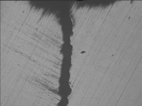
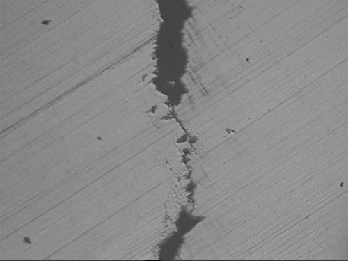
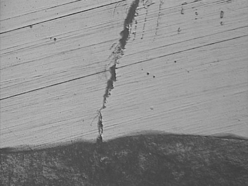
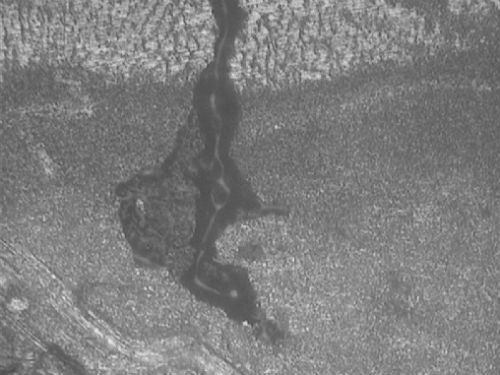
Photo 2. Nature of a crack in overaying.
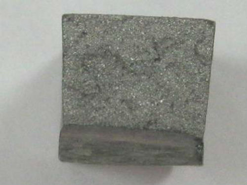
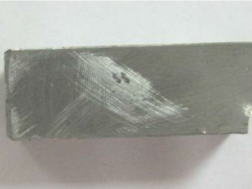
Photo 3. View of fracture of a sample.
2. Results of microscopic analysis
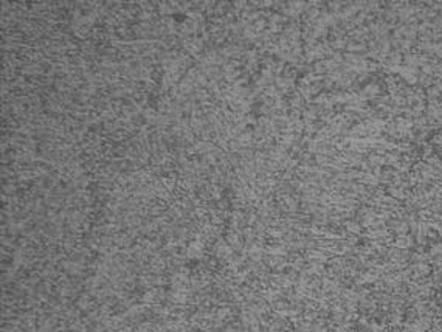
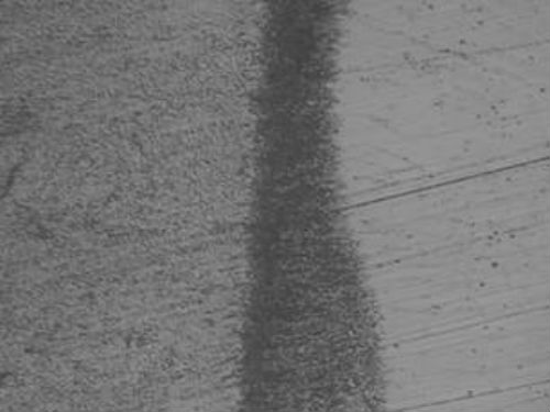
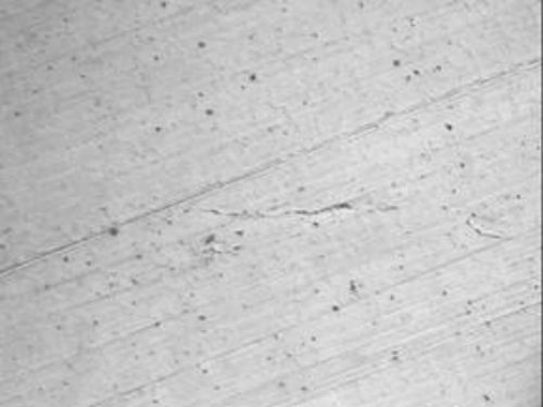
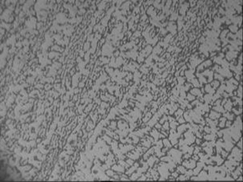
Photo 4. Microstructure of overlaying
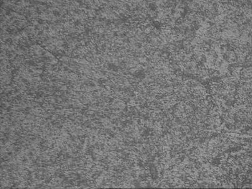
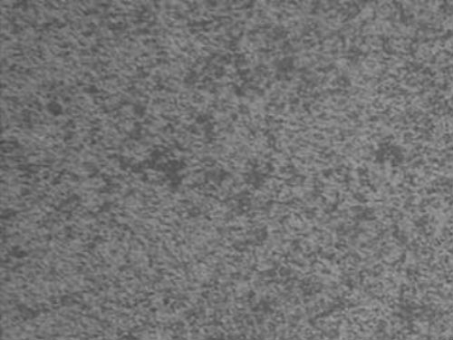
Photo 5. Microstructure of cross-section
